In this article we are going to get a thorough Understanding of :
1. Construction of 3 phase Induction Motor.
2. Types of 3 phase Induction Motor.
3.Comparative study among its types.
Table of Contents
ToggleConstruction of 3 phase Induction Motor
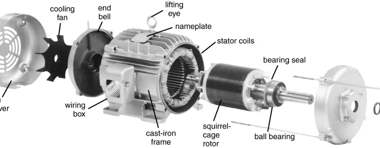
A 3-phase induction motor consists of two main parts: a stator and a rotor. The stator has a 3-phase winding that is connected to the 3-phase power supply. The rotor does not receive any external power. The rotor winding gets its voltage and power from the stator winding by means of electromagnetic induction. This is why it is called an induction motor.
1. Stator
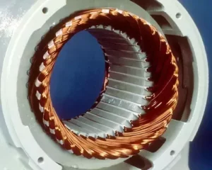
The stator has a steel frame that encloses a hollow, cylindrical core made of thin laminations of silicon steel. The core has several slots on its inner surface where the insulated conductors of the stator winding are placed. The stator winding can be connected in star or delta configuration depending on the required voltage and current ratings.

The number of poles in the stator winding determines the speed of the motor. The higher the number of poles, the lower the speed and vice versa.
The stator winding produces a rotating magnetic field of constant magnitude and frequency when it is supplied with 3-phase power. This rotating field induces an electromotive force and a current in the rotor winding, which creates another magnetic field in the rotor. The interaction between the stator and rotor magnetic fields causes the rotor to rotate and deliver mechanical power.
Types of Stator Slots
There are different types of stator slots that can be used in induction motors, such as open slots, semi-closed slots, and tapered slots.
Open slots have a slot opening equal to the slot width, which makes them easy to assemble and repair, but they also have a high air gap contraction factor, which leads to a poor power factor and high magnetizing current.
Semi-closed slots have a slot opening smaller than the slot width, which makes them more difficult to assemble and repair, but they also have a low air gap contraction factor, which leads to a better power factor and lower magnetizing current.
Tapered slots have a slot opening smaller than the slot width, and the slot width varies from top to bottom, with the minimum width at the bottom. This type of slot reduces the leakage reactance and tooth pulsation losses, but it also increases the cost and complexity of manufacturing.
The choice of stator slots depends on various factors, such as cost, weight, efficiency, cooling, temperature rise, overload capacity, etc. Generally, the number of stator slots per pole per phase is chosen as three or more for integral slot winding, and 3.5 for fractional slot winding. The number of stator slots should also satisfy the consideration of stator slot pitch at the air gap surface which should be between 1.5 to 2.5 cm.
2. Rotor
A hollow laminated core with slots on its outer surface is attached to a shaft and forms the rotor of an induction motor. The rotor winding, which is inserted in these slots, can be of two different types:
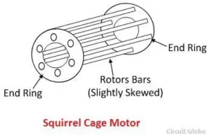
Squirrel Cage Type: This type of winding consists of uninsulated conductor bars that are short-circuited at both ends by end rings. The bars and rings form a cage-like structure that resembles a squirrel cage. The reason for using uninsulated bars is to reduce the eddy current losses and increase the efficiency of the motor. Conductors are skewed to prevent cogging during starting operation and gives better transformation ratio between stator and rotor.This type of winding has poor speed control because the rotor resistance is fixed and cannot be adjusted and low starting torque due to low resistance of conductor bars due to more cross sectional area.

Squirrel Cage Induction motor is used in applications where constant speed, high efficiency and low maintenance are required, such as fans, blowers, pumps, compressors, etc.
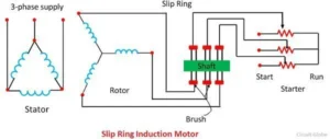
Wound Rotor Type: This type of winding consists of insulated coils that are connected in a three-phase star or delta configuration. The ends of the coils are brought out to three slip rings mounted on the shaft. External resistors or rheostats can be connected to the slip rings to vary the rotor resistance and control the speed and torque of the motor. This type of winding has better speed control and high starting torque because the rotor resistance can be increased or decreased by changing the external resistance.

Wound Rotor Induction Motor is used in applications where variable speed, high starting torque and smooth acceleration are required, such as cranes, hoists, elevators, conveyors, etc.
Difference between Squirrel Cage and Slip Ring Induction Motor:
| Basis of Comparision | Slip Ring Induction Motor | Squirrel Cage Induction Motor | |
|---|---|---|---|
| Rotor | Cylindrical laminated core with parallel slots and each slot consist one bar. | The slots of the rotor are not parallel, but are skewed. | |
| Construction | Complicated | Simple | |
| Resistance | Added external to the rotor | The rotor bar is permanently shorted at the end of the ring, thus it is not possible to add any external resistance. | |
| Starter | The rotor resistance starter can be used. | Rotor resistance starter can not be used. | |
| Starting Torque | High | Low | |
| Efficieny | Low | High | |
| Speed Control | Possible | Not Possible | |
| Power Factor | Low | High | |
| Cost | Costly | Cheap | |
| Starting Current | Low | High | |
| Uses | Use in hoist, cranes, elevator where high torque is required. | Use in lathe machines, fan, blower, profiting machines, etc. |
Recommended Books :
1.Electrical Machine by Dr. P. S. Bhimbra (Highly Recommended for GATE / IES)
2. Electric Machines by Ashfaq Husain and Harroon Ashfaq
3. Electric Machinery Fundamentals by Stephen Chapman
Some Related articles:
Click Here to learn about Control Systems
Click Here to learn about Rectifiers.
Discover more from WireUnwired
Subscribe to get the latest posts sent to your email.


