In this article, we are going to get a thorough understanding of:-
- Construction of synchronous generator
- Working of synchronous generator
- Speed and internal voltage of the synchronous generator
Synchronous generator (Alternator):
A synchronous machine which converts mechanical power into AC electric power through the process of electromagnetic induction is called a synchronous generator.
Synchronous generators are also known as alternators or AC generators. The name “alternator” comes from the fact that it generates AC power. The frequency of the AC power depends on the synchronous speed of the generator.
A synchronous generator can have either single-phase or poly-phase (usually 3phase) output. The number of phases determines the number of wires and coils in the generator.
Construction of Synchronous Generator:
If you want to understand how an alternator works, you need to know its two main components: the stator and the rotor. Let’s take a closer look at each of them.
The stator is the fixed part of the alternator that surrounds the rotor. It contains the armature winding, which is a coil of wire that generates the electric voltage when the rotor spins. The stator is connected to the output terminals of the alternator, where the electricity is delivered to the load.
The rotor is the rotating part of the alternator that spins inside the stator. It creates the magnetic field that induces the voltage in the armature winding. The rotor consists of an electromagnet that is powered by a small amount of current from the battery or another source. The rotor can be adjusted to change the strength of the magnetic field and thus control the output voltage of the alternator.

Stator Construction of Synchronous Generator:
In this, the main components of the stator of an alternator and their functions are explained. The stator is the stationary part of the alternator that generates the alternating current (AC) output.
The stator consists of four main parts: the frame, the core, the windings, and the cooling system.
– The frame is the outer casing of the stator that supports and protects the other parts. It is usually made of cast iron for small alternators and welded steel for large ones.
– The core is the inner part of the stator that carries the magnetic flux. It is made of thin sheets of silicon steel that are stacked together and insulated from each other. The silicon steel reduces the losses due to hysteresis and eddy currents in the core.
– The windings are the coils of wire that are placed in slots on the inner surface of the core. They are connected in a star configuration and form a three-phase armature circuit. The windings produce an AC voltage when they are cut by the rotating magnetic field of the rotor.
– The cooling system is the arrangement that keeps the stator at a suitable temperature. It may consist of air ducts, fans, water jackets, or oil circulation depending on the size and rating of the alternator.

Rotor Construction of Synchronous Generator:
In this blog post, I will explain how the rotor of an alternator works and what are the different types of rotor designs. The rotor is the rotating part of the alternator that produces the magnetic field. The magnetic field is created by a coil of wire called the field winding, which is connected to a DC source (also known as the exciter) through two slip rings. The exciter is usually a small DC generator that is attached to the same shaft as the alternator.
There are two main types of rotors for alternators: the salient-pole type and the cylindrical rotor type. The salient-pole type has projecting poles on the rotor, which are shaped to fit the stator slots. The cylindrical rotor type has a smooth surface with slots for the field winding. The salient-pole type is more suitable for low-speed applications, such as hydroelectric generators, while the cylindrical rotor type is more suitable for high-speed applications, such as steam turbines.
Salient Pole Rotor:
Salient pole rotors are a type of rotor used in alternators. They have poles that stick out from the rotor core, as you can see in the figure below. The poles are wound with field coils that are connected in series. When a DC flows through the field coils, it creates a magnetic field that alternates between the north and south poles along the rotor. This magnetic field interacts with the stator windings to produce an AC output voltage.

A salient pole rotor is suitable for low and medium speed alternators, such as those driven by diesel engines or water turbines. These alternators typically have a speed range of 120 to 400 RPM. There are some reasons why a salient pole rotor is not used for high speed alternators.
First, a salient pole rotor has a complex construction that cannot withstand the mechanical stresses at high speed. The poles are mounted on the rotor body and have to be securely fastened to prevent them from flying off due to the centrifugal force.
Second, a salient pole rotor causes windage loss and noise at high speed. The windage loss is the frictional loss due to the air resistance on the poles. The noise is the sound produced by the air turbulence around the poles.
Third, low speed alternators require a large diameter rotor to provide enough space for the poles. The poles have to be spaced apart to create a uniform magnetic field. A large diameter rotor also has a short axial length, which means that the rotor is wider than it is long. A salient pole rotor has this shape, while a high speed alternator needs a cylindrical rotor with a long axial length.
Cylindrical Rotor:
In this informative blog post, I will reveal the impressive workings of the cylindrical rotor and convincingly argue for its superiority over the salient pole rotor.
A cylindrical rotor is a type of rotor used in synchronous machines, such as generators and motors. It is made of high-quality steel that can withstand high stresses and temperatures.
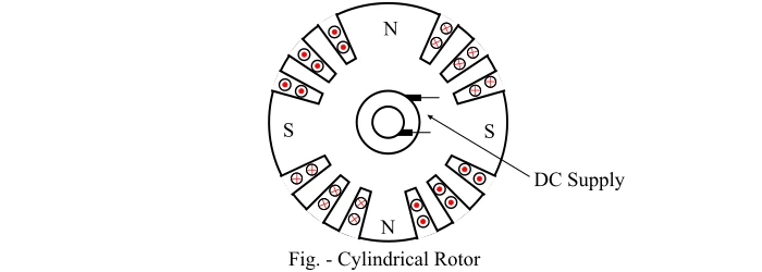
A cylindrical rotor has a smooth and round shape, unlike a salient pole rotor that has protruding poles on its surface. The cylindrical rotor has slots along its circumference, where the field coils are inserted. The field coils are energized by direct current and create a magnetic field around the rotor.
The slots occupy about two-thirds of the rotor’s surface, while the remaining part is unslotted and forms the pole faces. The pole faces are the regions where the magnetic flux is concentrated and interacts with the stator windings. The cylindrical rotor has non-salient poles, meaning that they are not visible or distinct from the rest of the rotor.
The cylindrical rotor has several advantages over the salient pole rotor, such as:
– It can operate at higher speeds without causing mechanical stresses or vibrations.
– It has a better cooling effect due to the air gap between the slots and the pole faces.
– It has a more uniform air gap and magnetic flux distribution, resulting in less losses and better efficiency.
– It has less windage losses due to the absence of protruding poles that create air resistance.
– It has less noise and maintenance requirements due to its simple and robust design.

Without a doubt, the cylindrical rotor construction is the superior choice for high-speed alternators driven by steam turbines. No other design even comes close in terms of efficiency and practicality. Let me explain why. These alternators have a speed range of 1500 to 3000 RPM and require a high mechanical strength and a low noise level.
The cylindrical type rotor construction consists of a smooth solid steel cylinder with slots on its surface to accommodate the field windings. The advantages of this design are as follows:
– It provides a greater mechanical strength and allows for more accurate dynamic balancing. This is important because any imbalance in the rotor can cause vibrations and damage the bearings and other parts of the alternator.
– It ensures a uniform air gap between the rotor and the stator. This reduces the noise level and the losses due to eddy currents and hysteresis in the stator core.
– It produces a nearly sinusoidal flux distribution around the rotor periphery. This results in a better EMF waveform and a lower harmonic distortion in the output voltage.
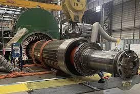
A cylindrical rotor alternator has a small diameter and a long axial length. This makes it suitable for horizontal installation. These alternators are also known as turbo-alternators or turbo-generators because they are often coupled with steam turbines.
Working of Synchronous Generator:
Synchronous generators are devices that convert mechanical energy into electrical energy. They are based on the principle of electromagnetic induction, which was discovered by Michael Faraday in the 19th century. Electromagnetic induction occurs when a conductor moves in a magnetic field, creating a voltage difference across the conductor. This voltage can drive an electric current in a closed circuit.
The working principle of a synchronous generator is as follows:
– The rotor is driven by a prime mover, such as a turbine, engine, or motor, at a constant speed.
– The rotating field magnets induce an alternating voltage in the armature windings, according to Faraday’s law.
– The frequency of the output voltage depends on the number of poles of the field magnets and the speed of rotation.
– The amplitude of the output voltage depends on the strength of the magnetic field and the number of turns of the armature windings.
– The phase of the output voltage depends on the position of the rotor relative to the stator.
A synchronous generator can operate in two modes: isolated or grid-connected.
In isolated mode, the generator supplies power to a local load without any external reference.
In grid-connected mode, the generator synchronizes its output voltage with an existing power grid, matching its frequency, amplitude, and phase. Synchronous generators are widely used in power plants, industrial applications, and renewable energy sources.
In a synchronous generator, the rotor is attached to the shaft and rotates at the same speed as the magnetic field (Ns). This means that the rotor’s magnetic field cuts through the stator’s armature conductors, which are fixed in place. This creates an electric potential difference and a current in the armature conductors. Each winding of the stator has a current that alternates in direction every half cycle, with a phase difference of 120° between them. This is how a synchronous generator produces a three-phase alternating current.
Speed of Rotation of Synchronous Generator:
Synchronous generators ensure precise synchronization between electrical frequency and mechanical rotation, a crucial factor for optimal performance. The rotor, energized with direct current, establishes a magnetic field aligned with its rotation. The correlation between stator electrical frequency (f) and the magnetic field’s rotation speed is expressed by f=NP/120
where , N= synchronous speed in RPM
P= number of rotor poles
Internal Voltage of Synchronous Generator:
To calculate the voltage induced by a rotating coil in a magnetic field, we need to consider two factors: the magnetic flux and the speed of rotation. The magnetic flux is the measure of how much magnetic field passes through the coil. The speed of rotation is how fast the coil spins in the magnetic field. The faster the coil spins, the more times it cuts through the magnetic field lines, and the more voltage is induced. The formula for the induced voltage is:
For simplicity, it may be simplified to as follows:
where;
To know more about synchronous generator Click Here.
Discover more from WireUnwired Research
Subscribe to get the latest posts sent to your email.


