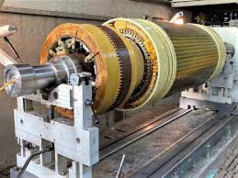
In the previous article on alternators, we discussed the construction, working, and generated voltage of a generator. If you haven’t read that article then Click Here to read that article.
In this article, we will go through a basic understanding of:
- Equivalent circuit diagram of synchronous generator
- Phasor diagram of synchronous generator
Equivalent circuit diagram of synchronous generator:
The equivalent circuit of an alternator or synchronous generator is shown in Figure-1. The equivalent circuit of the alternator is redrawn in Figure-2 by taking synchronous reactance 𝑋𝑆=𝑋𝐴𝑅+𝑋𝑎. By using the equivalent circuit, the phasor diagram of the alternator can be drawn as given below. By referring the equivalent circuit, we can write,
Phasor diagram of a synchronous generator:
In this article we discuss one of the easiest methods of making a phasor diagram for a synchronous generator.
A phasor diagram is a graphical representation of the magnitude and phase of alternating current (AC) quantities, such as voltage, current, and power. A phasor diagram can help us to analyze the behavior and performance of a synchronous generator under different operating conditions.
To draw a phasor diagram for a synchronous generator, we need to know the following quantities:
– Ef, which denotes the excitation voltage. This is the voltage induced in the rotor by the field winding.
– Vt, which denotes the terminal voltage. This is the voltage measured at the output terminals of the generator.
– Ia, which denotes the armature current. This is the current flowing in the stator winding.
– θ, which denotes the phase angle between Vt and Ia. This is the angle by which the terminal voltage leads or lags the armature current.
– ᴪ, which denotes the angle between Ef and Ia. This is the angle by which the excitation voltage leads or lags the armature current.
– δ, which denotes the angle between Ef and Vt. This is the angle by which the excitation voltage leads or lags the terminal voltage.
– Ra, which denotes the armature per phase resistance. This is the resistance of the stator winding.
In this blog post, we will derive the expression for the excitation emf in a synchronous generator for different power factors. The excitation emf is the voltage induced in the armature winding by the rotating magnetic field of the rotor. The power factor is the ratio of the real power to the apparent power delivered by the generator to the load. The power factor can be lagging, unity or leading depending on the nature of the load.
– Generating operation at lagging power factor
– Generating operation at unity power factor
– Generating operation at leading power factor
Phasor Diagram of Alternator for Lagging Power Factor Load:
If you want to understand how an alternator works when it delivers power to a load with a lagging power factor, you need to look at the phasor diagram. A phasor diagram is a graphical representation of the voltage, current and power in an AC circuit. In this post, I will explain how to draw the phasor diagram of an alternator with a lagging load, using Figure-3 as an example.
Figure-3 shows the phasor diagram of an alternator with a lagging load. The power factor is 𝜑, which means that the current Ia is delayed by an angle 𝜑 with respect to the voltage V. The voltage V is the reference phasor, and it points along OA, where OA = V.
The current Ia points along OB, where OB = Ia. The armature resistance IaRa causes a voltage drop that is in phase with the current, and it is shown by the phasor AC. The synchronous reactance IaXS causes another voltage drop that is 90° ahead of the current, and it is shown by the phasor CD. The total voltage drop in the synchronous impedance is the vector sum of AC and CD, and it is shown by the phasor AD. The actual generated voltage Ea in the alternator is the phasor OD, which is equal to V + AD.
This phasor diagram helps us to calculate the power output and efficiency of the alternator, as well as to determine the excitation required for a given load. In general, a lagging power factor reduces the power output and efficiency of the alternator and increases the excitation current.

Phasor Diagram of Alternator for Unity Power Factor Load:
The phasor diagram of the alternator supplying a load of unity power factor is shown in Figure 4. From the right-angled triangle OCD, the magnitude of the actual generated voltage can be determined as follows −
Phasor Diagram of Alternator for Leading Power Factor Load:
The phasor diagram of the alternator supplying a load of leading power factor is shown in Figure 5. From the right angled triangle OFD, the magnitude of the actual generated voltage can be determined as follows −
In the upcoming article, we will discuss the input and output power of the alternator, the effect of load on the alternator, parallel operation of the alternator, and alternator ratings.
Discover more from WireUnwired
Subscribe to get the latest posts sent to your email.


